15 lb Battlebot - Horns of Fury

A 15 lb battlebot designed for and entered into the SXSW Battlebots - Metal Mayhem competition. The battlebot placed 2nd in it's group and won the four bot rumble.
Published on March 11, 2024 by John Lyle
Robotics Design Electronics
Summary
Final Product:
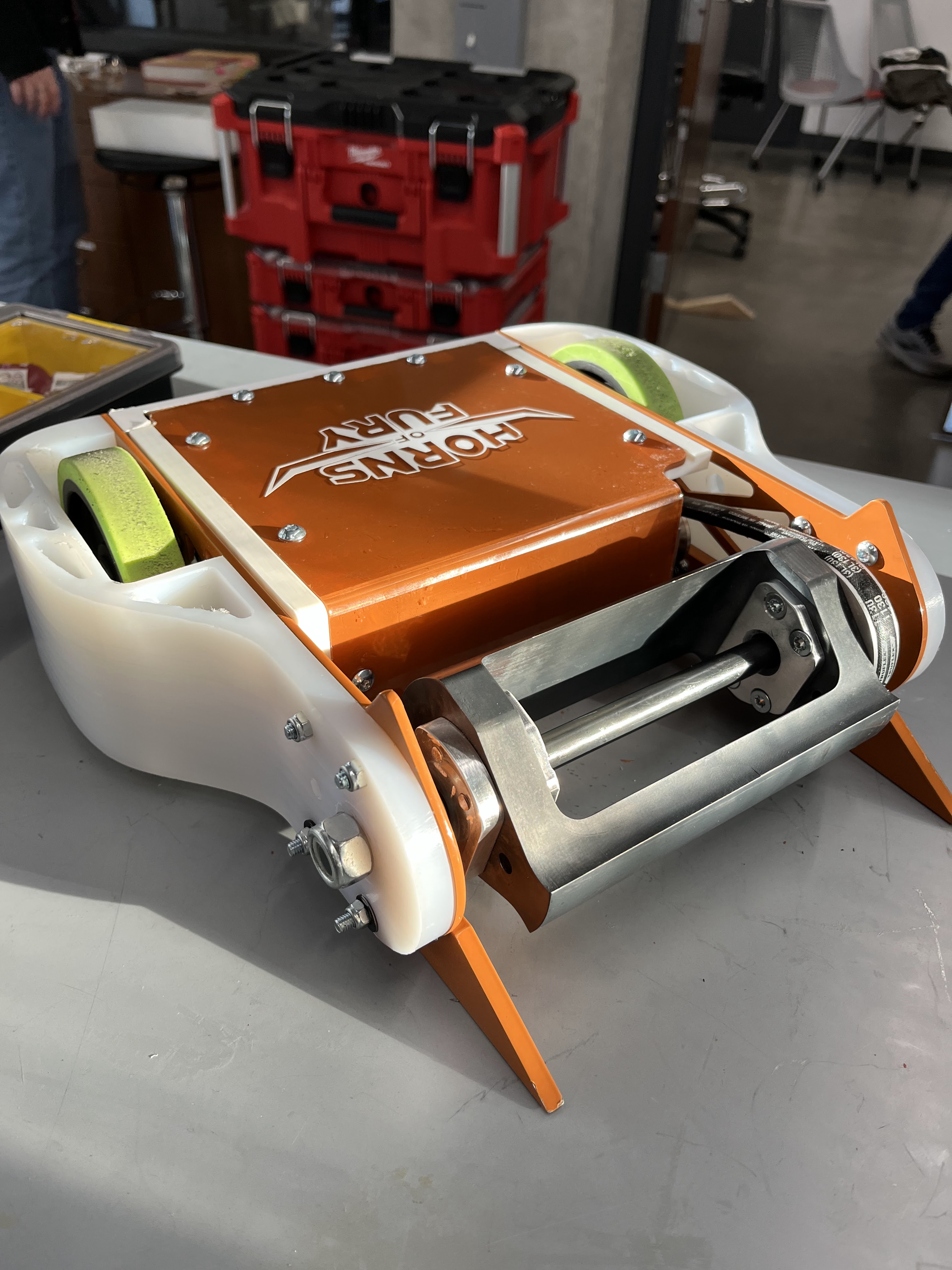
Problem Statement: In 5 weeks design and fabricate a 15 lb robot to represent UT Austin at the SXSW Battlebots - Metal Mayhem competition.
Project Timeline: Due to the extremely tight deadline our group decided to build an eggbeater style vertical spinner based robot, a strategy many of us had experience with. We began the design process by researching other bots in this weight class to determine our required specs. Next we selected all of the off the shelf components we would be using and began the CAD for the rest of the bot. Since we would not have time for any revisions we had to make sure the first round of parts we ordered and manufactured would work. This led us to have many design reviews focused on safety requirements, design for assembly, and the ability to easily swap components. Once all of the components had arrived and been manufactured we began building and testing the robot to catch any improvements we could make in house at Texas Inventionworks. The last week before the competition was a frenzy of making improvements, practicing quickly repairing and rebuilding the bot, and developing a competition day strategy. Overall we placed second in our group and won the rumble which is where 4 robots were placed in the arena at the same time.
Individual Contributions: I served as the electronics lead for this project. This included determining required specs and selecting electronic components, calculating necessary battery size, and setting up the transmitter and working with the driver to meet their requirements. In addition to this I managed our competition day strategy and led the efforts to diagnose and repair the bot between matches. Throughout the whole process I participated heavily in the manufacturing process by using a CNC to mill components as well as designing a few 3D printed components for use in the electronics subassembly.
Design Process Overview
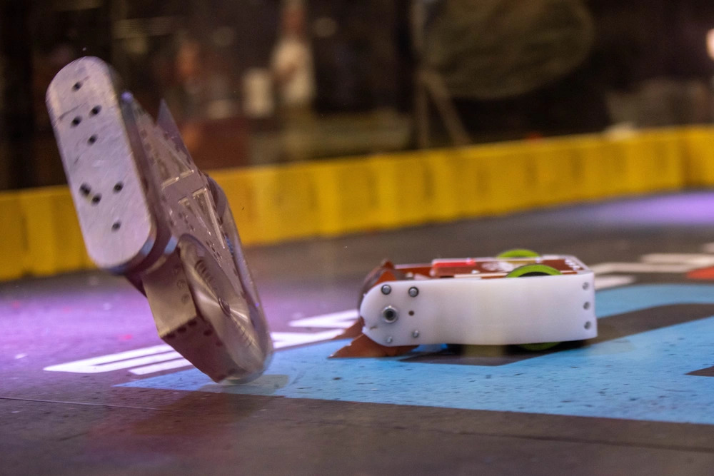
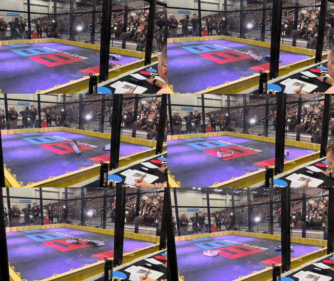
Offensive and Defensive Strategy: Once we had settled on an eggbeater style weapon we focused our offensive strategy on causing as much damage as possible in every hit. This meant spinning the weapon up as quick as possible and being aggressive with our driving. In addition to this we had a few variations of our front wedges in order to improve effectiveness against various bots. Due to focusing on an aggressive offensive strategy we increased the likelihood of taking hits as well. Our defensive strategy was centered around adaptability and an ability to take hits and still function to accommodate for our aggressive offense. We accomplished this by designing the robot to be able to drive upside down and selecting materials that can absorb energy well.
Combat Image
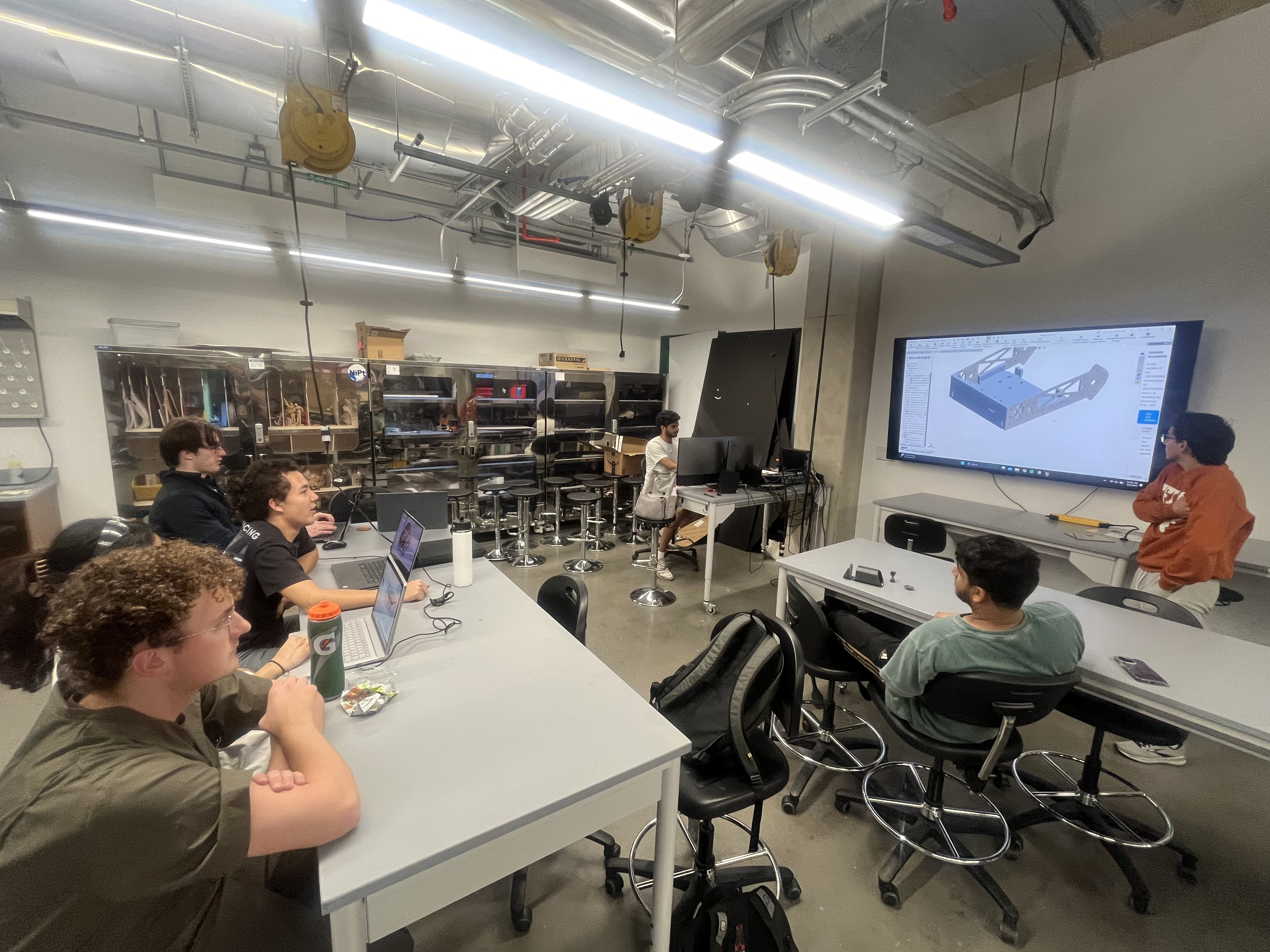
Design: During the design stage we had multiple team design reviews and spoke with a few mentors regarding our competition strategy. Through advice from experienced combat robotics drivers we were able to add many little touches to improve our chances of success. In the design reviews we made sure to thoroughly talk through steps of assembly and safety regulations with the whole team so that we could catch any mistakes.
Team Meeting
Manufacturing and Assembly: After the design was finalized we sent off drawings for any parts that could not be manufactured in house and began machining the rest of our components. We also 3D printed models of any parts that would not arrive till closer to the competition in order to practice assembling the robot. During the assembly stage we ran into some errors with tolerancing of our ordered parts and had to make a few last minute design modifications to remedy this.
Assembly Picture
Personal Contributions
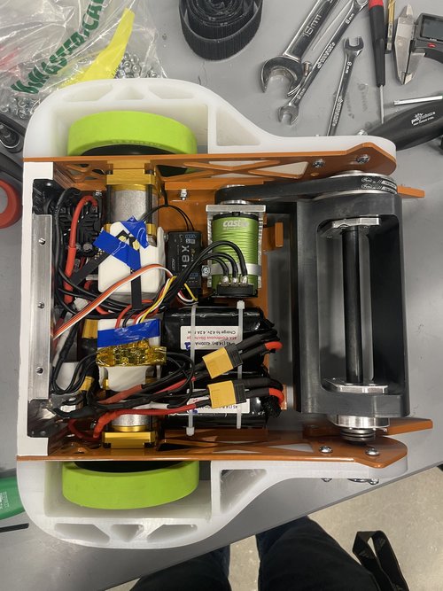
Electronics: I was in charge of the electronics subassembly for this battlebot. In order to begin my work, I first worked with the team to determine desired top speed and acceleration of the bot and the weapon. Using these numbers, I figured out torque and rpm requirements for motors. Once motors were selected, I was able to determine how large of a battery to select. When selecting disconnects and wires, one of my main focuses was to make sure we could easily swap out all of the components quickly without soldering anything. This was crucial for competition day in case we ran into any issues with the electronics.
Electronics Diagram
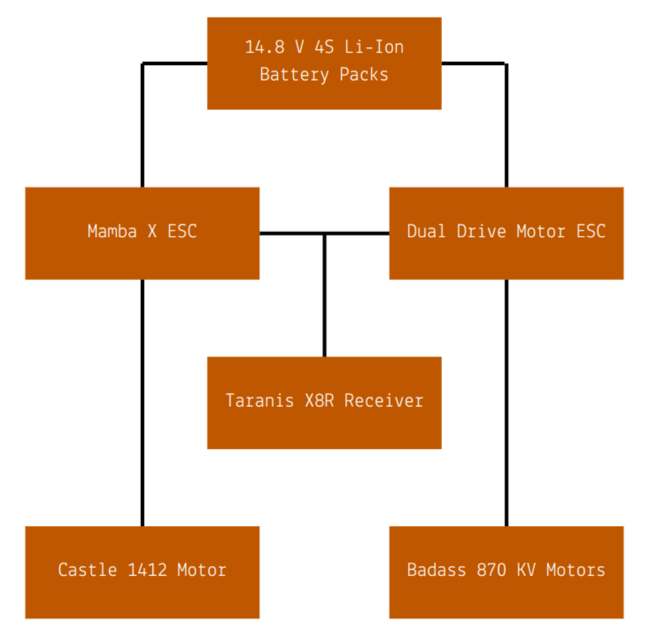
Controls: Another thing I was tasked with for this project was selecting a transmitter and receiver for the bot and working with the driver to customize the controls to his liking. One of the key things that I implemented was a switch for if we got flipped upside down. This switch modified all of the controls to allow our driver to continue driving as if the bot were still upright. I also implemented safety shutoffs in case the receiver ever lost signal; all motors would lose power as well.
Upside Down Controls
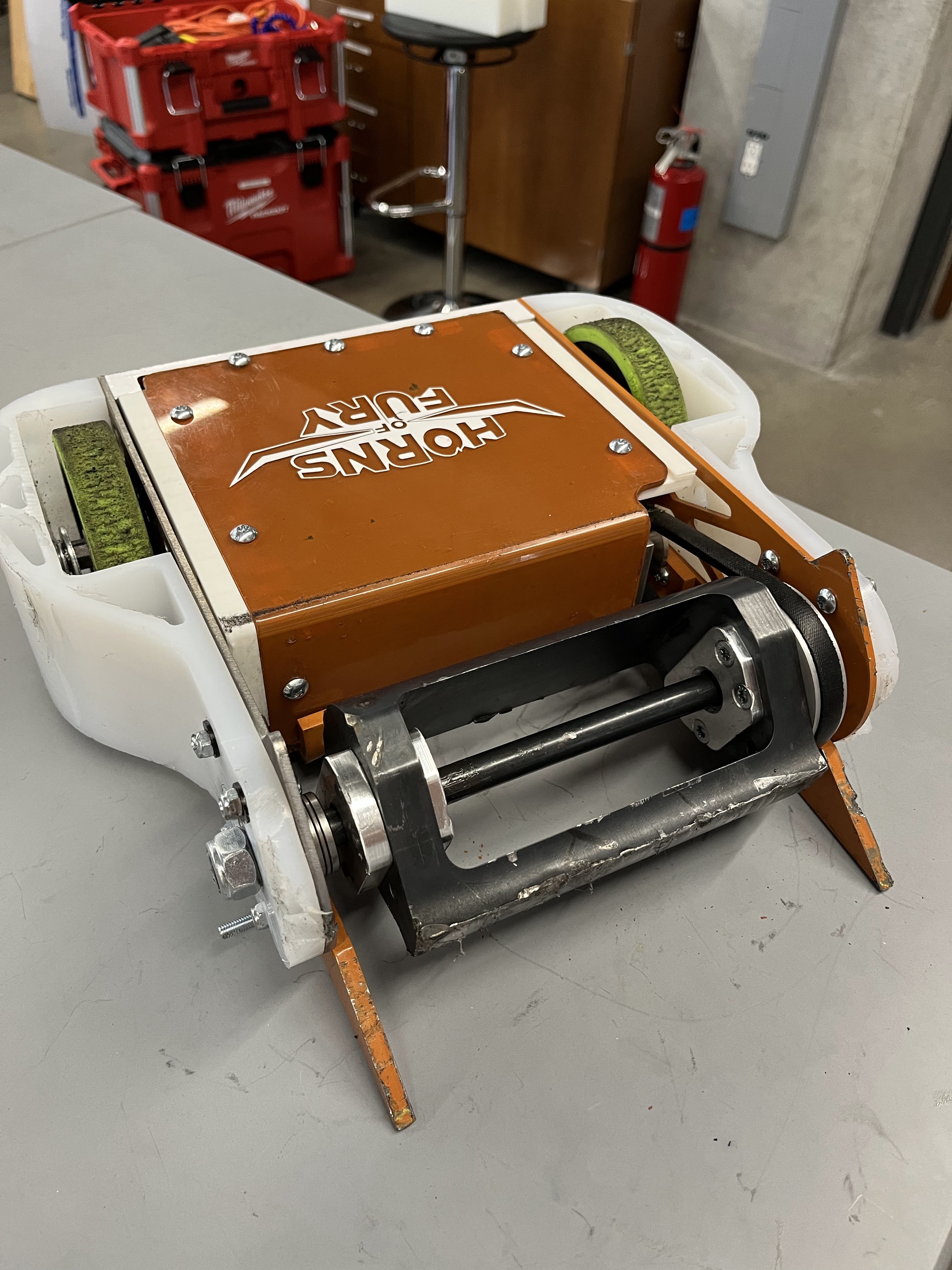
Repairs and Diagnosing Competition Day Problems: In the days leading up to the competition, one of my main focuses was thinking through any issues we might run into and setting up our repair process between matches. Since we would only have 30 minutes between matches, it was important to be able to quickly diagnose any electronics issues we had while simultaneously replacing any of the other components. In order to most efficiently do this, we used our spare parts to assemble a second bot so that we could quickly swap over the receiver and have another operational bot.
Post Competition Picture
Key Takeaways and Skills Utilized
This project was some of the most fun I have had as an engineer. Working with some of my best friends to design and build an incredibly successful bot in only 5 weeks was incredibly challenging. It gave me the chance to apply so many things I had learned about in classes and also learn so much more.
Skills Used
- Dynamics Analysis
- Max Discharge and Battery Life Calculations
- Solidworks
- CNC Mill Machining
- Manual Mill Machining
- 3D Printing
- Failure Analysis
Additional Information
More information on this project can be found in the design binder. For any further questions regarding design, strategy, or part and material selection please contact John Lyle.