Handheld Controller

A handheld controller designed to be integrated with a teleoperation exoskeleton to expand user inputs.
Published on October 03, 2023 by John Lyle
Circuit Design CAD ROS
Summary
Demonstration: The below video shows me using the controller in my left hand to assist in teleoperation.
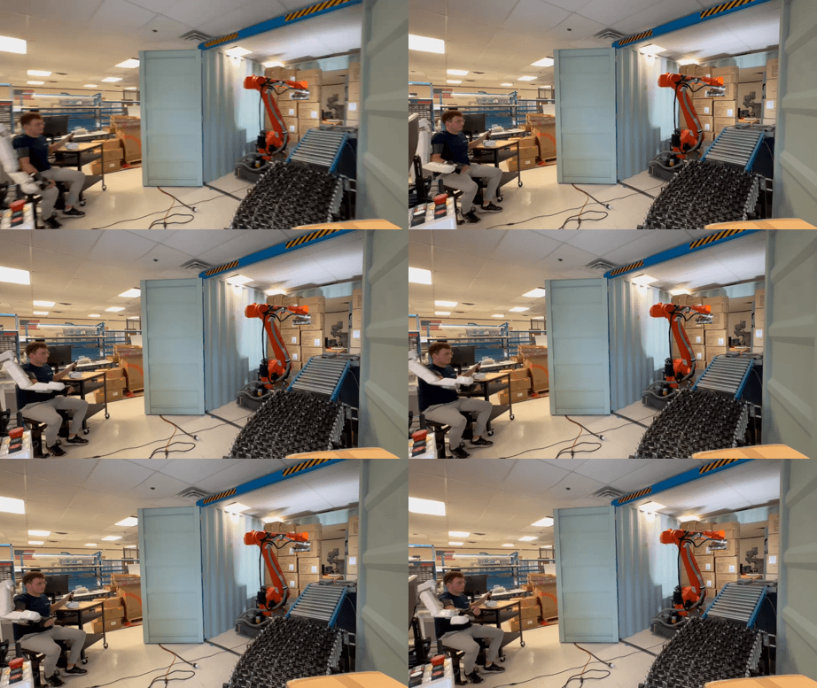
Problem Statement: Create an ergonomic controller that integrates 1 analog input and 4 digital inputs from the user. All inputs must be sent through 2 analog signals and all inputs must be usable with the hand in a closed grasp position. In addition, I also had to create a ROS node for decoding the analog signals and triggering the associated functions.
Project Timeline: This project was given to me during my robotics engineering internship at Contoro Robotics. First, I designed the circuit that allowed me to send 1 analog input and 4 digital inputs through 2 analog signals. Next, I iterated through many prototypes of main body designs. Using feedback from my coworkers, I arrived at a base design that was comfortable to hold. Unfortunately, the grip still wasn’t comfortable enough for continuous use over an extended period of time. I then decided to pivot to a consumer pilot stick from Logitech. I disassembled this pilot stick and implemented my circuit by modifying the included PCB as well as replacing the output USB cable with the required connector for my use case. Once the controller was ready to be implemented, I mounted it on the exoskeleton and performed a calibration. Finally, I created a ROS node for decoding the signals and performing the desired functions.
Engineering Process Overview
Circuit Design: The circuit below shows my design for converting 4 digital inputs into 1 analog output. The value R can be any resistance as long as the ratio between them stay approximately the same as shown below. I used surface mount resistors to implement this circuit on the PCB I modified. This circuit creates unique voltage readings at each possible combination of button presses to allow for simultaneous use of all 4 buttons.
Resistor Ladder Circuit

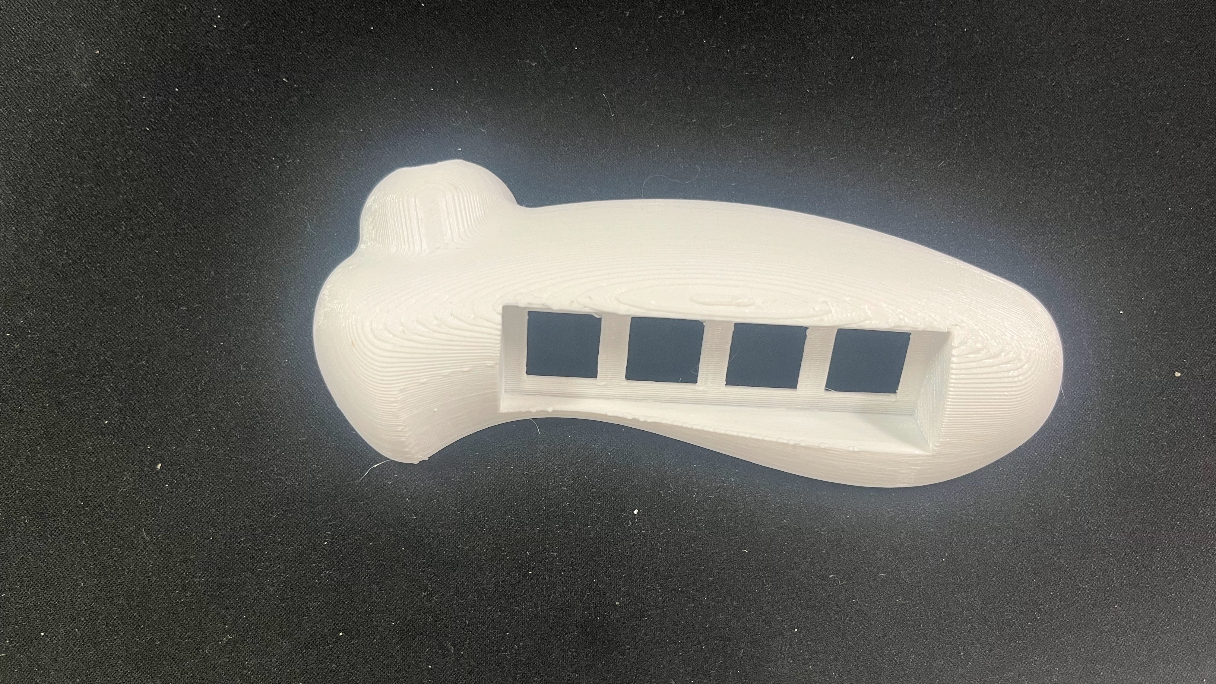
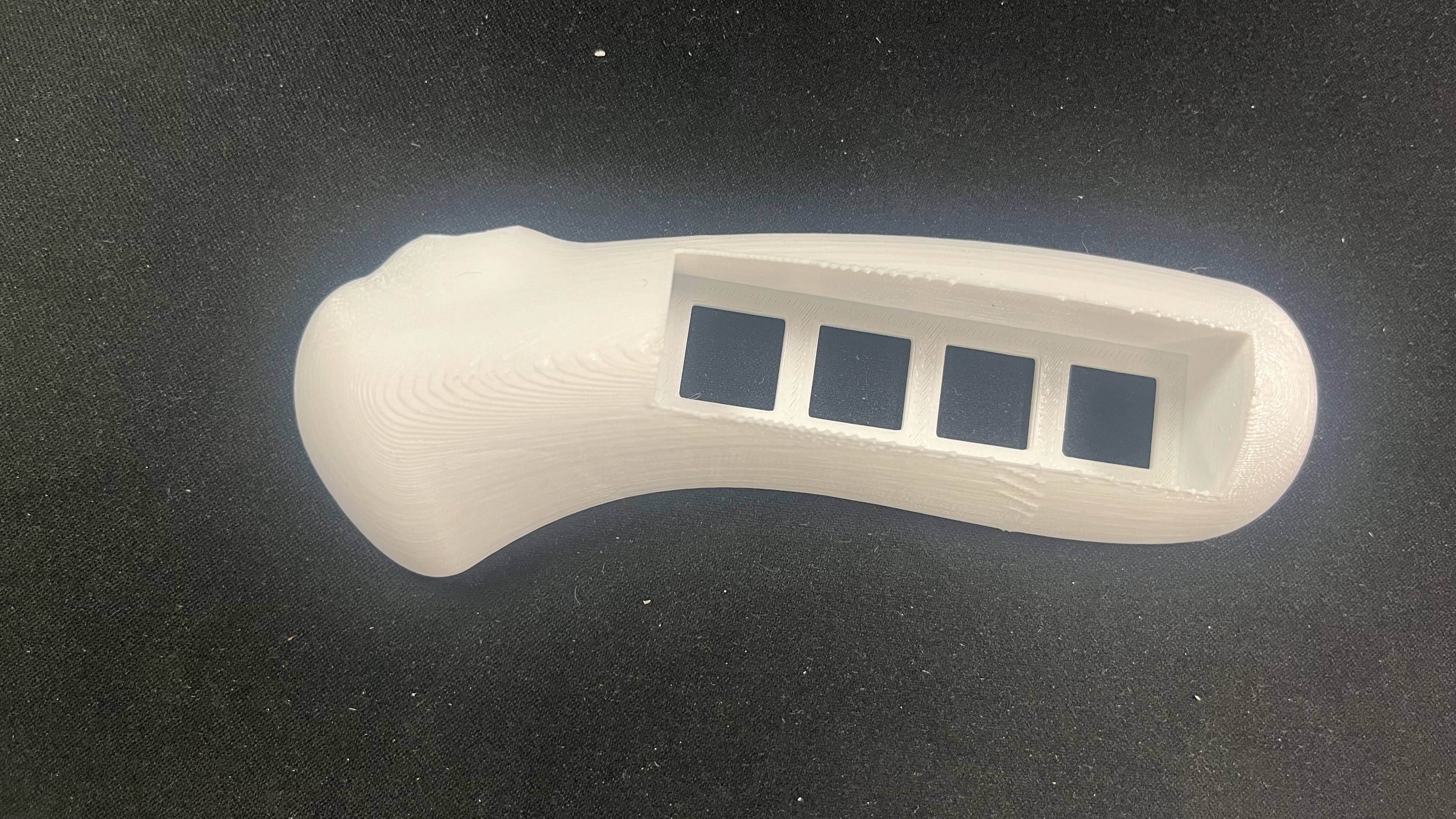
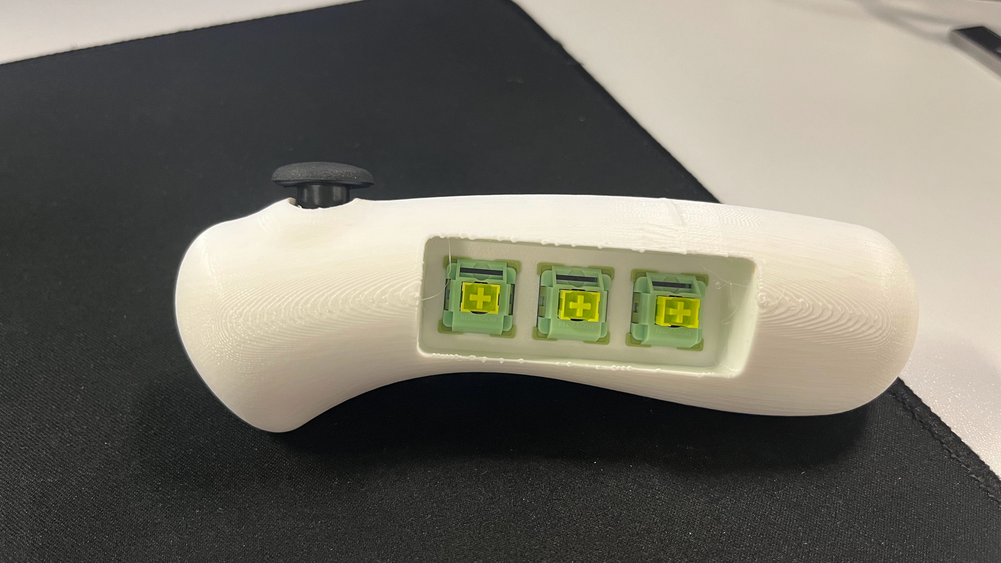
Prototyping: Before switching to an off the shelf component I iterated through many designs to attempt to achieve an ergonomic solution as shown in the photos below. Ultimately given the time constraints of the project I had to pivot since this iterative process while showing promise would have taken too long. The Logitech controller only had digital inputs so I decided to use 8 digital inputs sent across 2 analog signals.
Version 1
Version 2
Version 3
Implementation and Calibration: Once I implemented the aforementioned circuit in the Logitech controller I setup an Arduino to collect data as I pressed each combination of buttons. This data was then sent through a Python algorithm I created to automatically determine what range of readings to associate with each combination of presses. This Python algorithm then output a few lines that could be copy and pasted into a config file on the device the controller was integrated with.
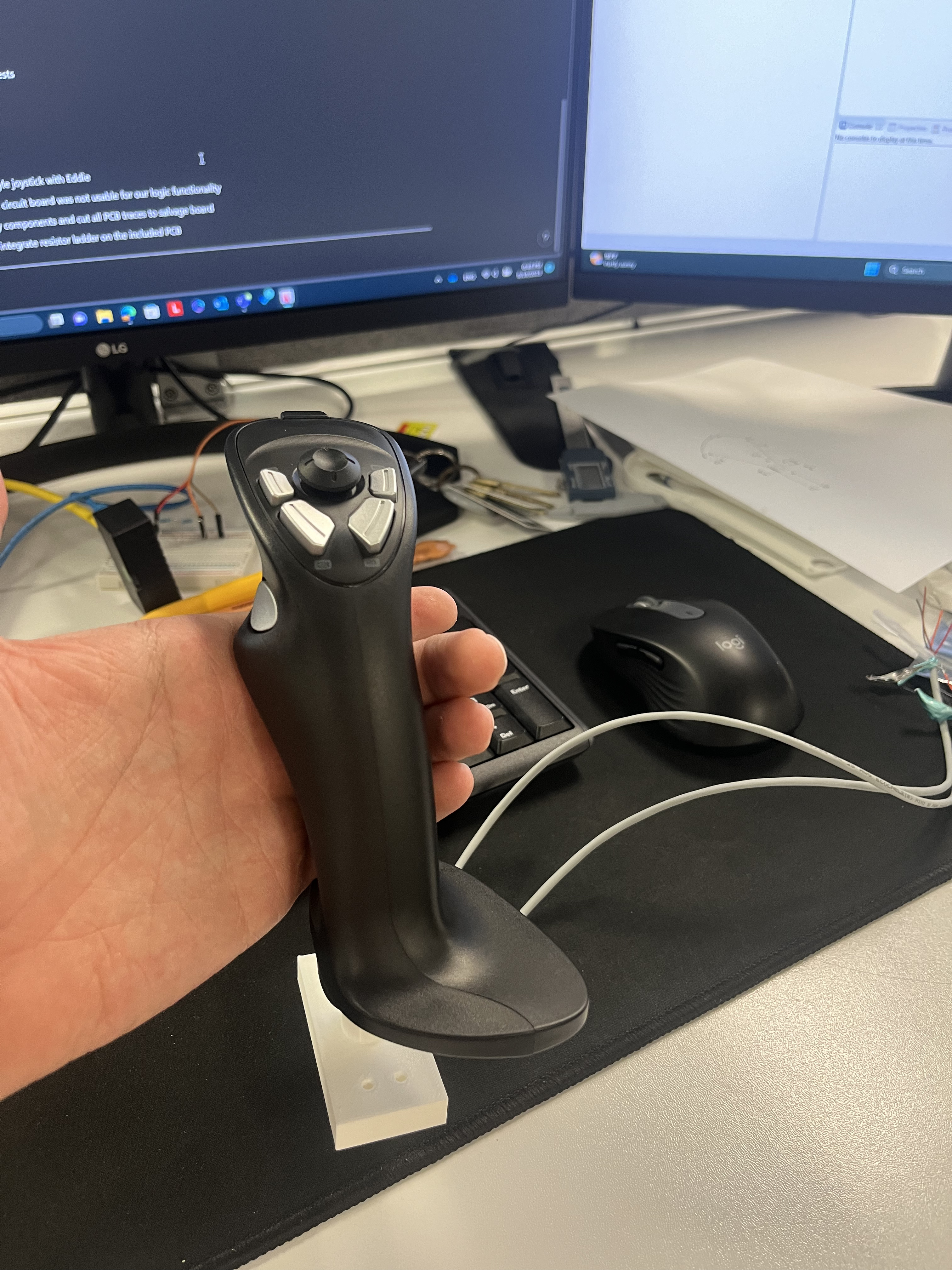
ROS Compatibility: Since ultimately this controller needed to interface with ROS I created a node to decode the button presses and communicate the corresponding controls. In addition to this I also setup a numpad to be used in ROS to communicate controls as well.
Key Takeaways and Skills Utilized
This project was a great opportunity to apply my learnings in ROS and circuit design and taught me a lot about signal processing. One of my main takeaways was that off the shelf solutions are almost always cheaper and more time efficient.
Skills Used
- Python
- ROS
- Arduino programming
- Circuit Design
- Solidworks
- 3D Printing
- SMD Rework